Product Series Description
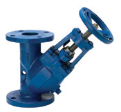
Our ETDV triple duty valves are primarily required on the discharge side of a centrifugal pump in a hydronic heating or cooling system. The valves functions as a shut-off valve, spring loaded silent check valve, and balancing valve.
Our ETDV has an automatic and silent operation. The disc will open when the line pressure is approximately 1/4 PSI. As the line pressure approaches zero, the spring will close the disc to prevent flow reversal and water hammer. The flow through the valve can be adjusted from bubble tight shut-off to full flow by the acme rising stem.
The center guided soft seal disc ensures that there is no leakage. The rising stem design includes an adjustable position indicator for accurate disc positioning for throttling service. The unit comes with a standard gauge taps at both the inlet and outlet sides and a NPT drain plug.
Our ETDV’s are constructed from rugged cast iron castings that are machined to exacting specifications. These bodies have drilled flanges that are in accordance with ASME B16.1.
Features & Benefits
3 Valves in 1 | A triple duty valve replaces a balance valve, shut-off valve, and a check valve. |
---|---|
Flanges | Valves are complete with FF flanges in accordance with ASME B16.1. |
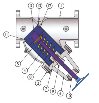
Automatic & Silent Operation | The valve is spring loaded to ensure that the disc closes as the line flow approaches zero. This feature prevents water hammer. |
Line Pressure | Line pressures of approximately 1/4 PSI will open the disc. |
Flow Adjustment | Flow through the valve can be adjusted from zero to full flow by the ACME rising stem. |
Bubble-Tight Sealing | Soft-seated dovetail O-ring groove ensures bubble-tight sealing when the valve is positioned in the fully closed position. |
Graduated Position Indicator | The rising stem incorporates a graduated position indicator to ensure accurate disc positioning for the throttling service. |
Hand-Wheel | All valves supplied with hand-wheel for ease of operation. |
Connection Plugs | Drain and differential connections are furnished with a plug as standard. |

Dimensional Data
Size in/mm |
A in/mm |
B in/mm |
C in/mm |
D N.P.T. in/mm |
E N.P.T in/mm |
Weight lb/kg |
2 50 |
8.38 213 |
9.63 244 |
6.25 159 |
1/2 15 |
1/4 8 |
34 15 |
2 1/2 65 |
9.88 251 |
10.00 254 |
6.25 159 |
1/2 15 |
1/4 8 |
40 18 |
3 80 |
10.00 254 |
10.13 257 |
9.38 238 |
1/2 15 |
1/4 8 |
50 23 |
4 100 |
14.50 368 |
12.63 321 |
9.38 238 |
1/2 15 |
1/4 8 |
100 45 |
5 125 |
16.00 406 |
16.38 416 |
11.00 279 |
1/2 15 |
1/4 8 |
155 70 |
6 150 |
18.00 457 |
17.50 444 |
11.00 279 |
3/4 20 |
1/4 8 |
200 91 |
8 200 |
21.50 546 |
18.50 470 |
12.50 317 |
3/4 20 |
1/4 8 |
350 159 |
10 250 |
22.50 648 |
21.75 552 |
12.50 317 |
1 25 |
1/4 8 |
480 218 |
12 300 |
30.00 762 |
24.50 622 |
12.50 317 |
1 25 |
1/4 8 |
898 408 |
14 350 |
30.38 772 |
29.63 753 |
12.50 317 |
1 25 |
1/4 8 |
898 408 |
16 400 |
35.50 902 |
32.63 828 |
12.50 317 |
1 25 |
1/4 8 |
1172 533 |
Notes
- Dimensions shown are subject to change.
- Dimensions are given in full open position.
Parts List
Item | Description | Specification |
---|---|---|
1 | Valve Body | A126-B Cast Iron |
2 | Cover Flange | A126-B Cast Iron |
3 | Valve Disc | A536 Nickle Plated/Bronze B62 |
4 | Valve Stem | Type 410 Stainless Steel |
5 | Valve Seat Guide | A536 Nickle Plated Ductile Iron |
6 | Flange Gland | A126-B Cast Iron |
7 | Packing | Non-Asbestos |
8 | Valve Spring | 300 Series Stainless Steel |
9 | Packing Gland | A126-B Cast Iron |
10 | Valve Stem Guide | A536 Ductile Iron |
11 | Valve Seat Ring | A536 Nickle Plated Ductile Iron |
12 | Valve Seat Seal | EPDM O-Ring |
13 | Valve Disc Seat | EPDM O-Ring |
Parts Diagram

Performance Data
Size (in) | 2 | 2 1/2 | 3 | 4 | 5 |
Size (mm) | 50 | 65 | 80 | 100 | 125 |
CV | 82 | 128 | 188 | 334 | 497 |
Size (in) | 6 | 8 | 10 | 12 | 14 |
Size (mm) | 150 | 200 | 250 | 300 | 350 |
CV | 701 | 1079 | 1826 | 2430 | 3225 |
Notes
- Values are Cv rating at 100% of stem rise.
- Cv is defined as the volume of water that will flow through a given restriction or valve opening with a pressure drop of one (1) PSI at room temperature.
- Maximum pressure drop should not exceed 10 PSID.
- For balancing a recommended 1.5 PSID of pressure drop is required for flow determination.
Operational Limitations
Upper Pressure Limits (Non-Shock)
Elbi Series | Body Material | M.A.W.P. PSIG (Bars) |
ETDV | A126-B | 200 (13.79) Sizes <= 12″ 150 (10.34) Sizes >= 14″ |
Note: Pressure-temperature ratings in accordance with ASME B16.1. Temperature limited by seal material.
Upper Temperature Limits
Seal Material | Upper Units °F (°C) |
BUNA-N | 212 (100) |
EPDM * | 250 (121) |
VITON | 400 (204) |
* Standard seal material is EPDM.
Lower Temperature Limits
Body Material | Upper Units °F (°C) |
A126-B | -20 (-28.9) |
Downloads
- EOA Pressure Drop Chart ETDV 2016-1
- Triple Duty Valve OM Product Manuals
- Triple Duty Valves Sheet Catalog Items, Submittal Data Sheets